Friday, June 8, 2018

Gripper Unit Assembly


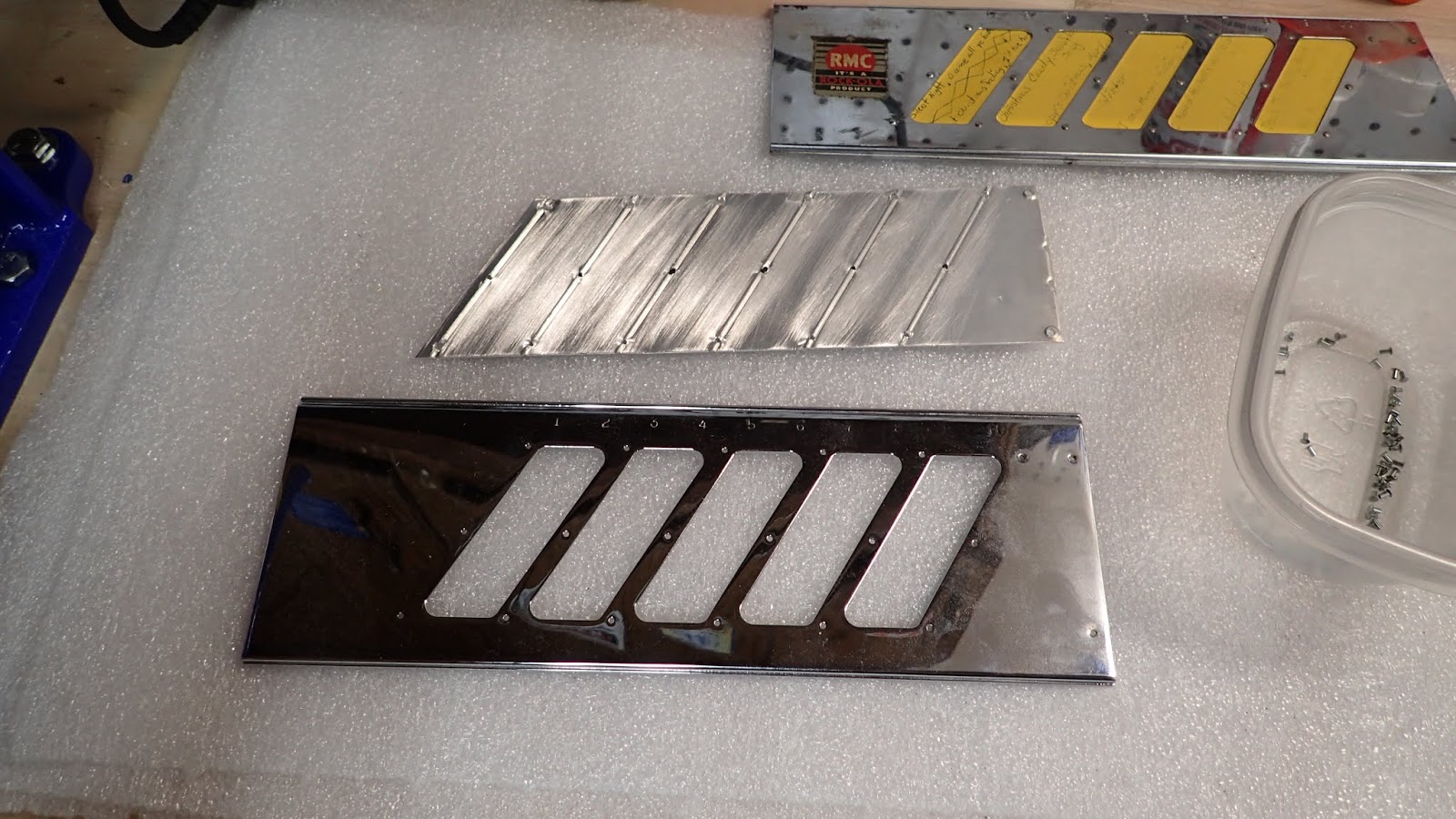
Assembly of the Gripper Unit started with laying out all of the parts, with everything shown here having been previously either plated, painted, or thoroughly cleaned:


As an aside, I had previously done some assembly work on the mechanism baseplate/frame, installing the "rear frame/mount", and the Gripper Connecting Rod and reversing mechanism/lever, as seen here (rear view):


And here (front view):


The Gripper Connecting Rod needs to be installed in this opening before bolting down the Gripper Housing:


Note the Micro Switches, and spacers, have been installed as well.

Before bolting-down the Gripper Housing I temporarily installed the External Shaft to (hopefully!) ensure the opening/bearing at the "rear mount" was aligned with the Gripper Housing bearing, as even a slight misalignment could cause binding. Thankfully once I tightened things up the shaft rotated as smooth as silk!

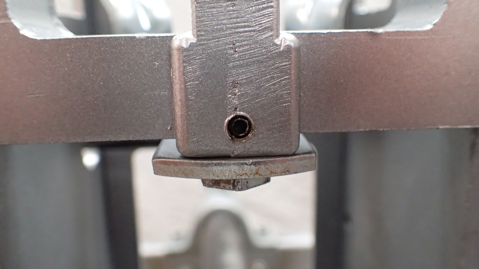
Note that the factory did provide bolts for adjusting the height of the "rear mount" to line-up with the Gripper Housing, but (and here I am making an assumption) once they got everything lined-up they made things permanent by drilling and "pinning" the "rear mount" to the "rear frame":


My thoughts on this are that if someone were to use a Gripper Housing and "rear mount/frame" from two different units, the pins may need to be drilled-out and the openings aligned.

Moving on, the end of the Gripper Connecting Rod has two clips which connect to the Gripper Reversing Bracket Assembly:


Which mounts to the Gripper Housing by a Shoulder Bolt:


I could not find a torque, procedure, or setting, for the shoulder bolt, so I simply tightened it up until the Reversing Bracket Assembly seemed to be "too tight", and then I backed it off just a bit. Note there is an Allen-head setscrew for this bolt, and I "locked-in" the adjustment of the Shoulder Bolt with this set screw.

Keen eyes will note that the threads of this bolt appear to be somewhat stripped-out, no doubt from a previous owner or serviceman removing the bolt without knowing the setscrew was there because of layers of crud! In fact, I have three of these assemblies, and all of them have suffered the same fate. This bolt, while appearing to be stripped, was actually quite "use-able", and the best of the three that I have!


The next thing I did was to assemble the Trunnion Shaft,"Geneva Gripper Turnover" cam ("inner" cam), and Gripper Spider Assembly. The Spider Assembly is located at the top of, and in-between the "ears of, the Gripper Housing, and is shown here with "Record Playing" text. The Trunnion Shaft simply slips into the housing, and Spider Assembly, with some lube. (I'll talk more about lube at the end of this post).

 
Pay no attention to that "extra" cam, as I found that I was premature in installing it!

Anyway, the "inner" cam simply slides onto the Trunnion Shaft, and is connected via a pin from the Spider Assembly:


So far, so good.....

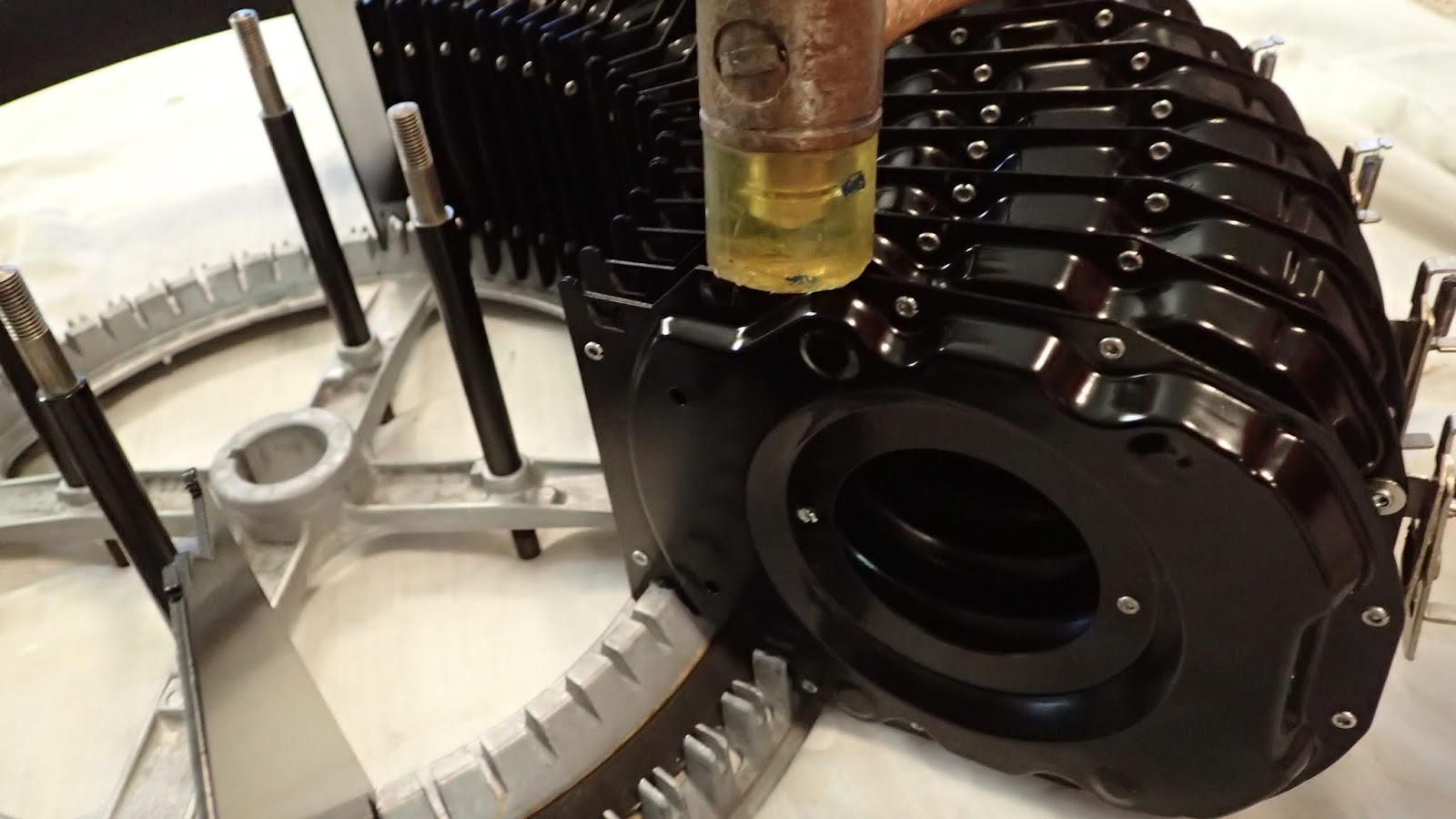
Before installing the Gripper Drive Shaft Assembly, this red washer needs to be installed....


And lubed:


Ok, here's where things get tricky, or at least they did for me!

While attempting to install the Gripper Drive Shaft Assembly I recalled that the Geneva Gripper Release cam (or "outer" cam) could not be installed previously, as the "flange" from the Drive Shaft needs to reside behind the outer Geneva cam!

(I can hear you already: "Huh?")

Here's what I'm talking about:


On the shaft "sticking out" the right side, ultimately that flange needs need located "behind" (or "inside") the outer cam, and to be precise, "below" the inner cam. And with that outer cam in place, you can't get there from here.....

So I had to remove the outer cam, slide the Drive Shaft Assembly in, make sure everything was lined-up/"clocked" correctly....


And it was only when I got to this point that I could re-install the outer cam:


For reference and/or comparison purposes only, here's the "timing" of the Geneva cams on my Parts unit:


As well as shot of the Geneva cams for the completed assembly for this unit (this picture taken way out of context/time):


I shot a quick video of what things should look like, and how it should operate at this point, and uploaded it to Youtube. It can be seen here:

https://youtu.be/g4E7AI2s5mg

Yes, that's my voice....

My advice to anyone doing this: Take your time, be patient, and don't try to "force" anything. Be aware that there is more than one way of assembling these parts, but only one way they will go together successfully! If, when operating the mechanism by hand, it doesn't seem like it's working right, it's simply not assembled correctly.

(1/16/19 Edit: I've had to remove and reinstall the Gripper Drive Assembly several times recently (reasons for which will be explained when appropriate), and I've found that I do NOT need to remove the Outer Cam gear in order to install the Gripper Drive Shaft Assembly! In fact, now that I've learned this, it's much easier to service this mechanism.)

Next I needed to install the Gripper Arm and related parts:


After applying a liberal amount of lube, I installed the Inner Gripper Casting into the arm, and installed the Gripper Arm into the Gripper Spider Assembly.


Here's a shot from the rear, before I installed the Gripper Spring:


After the Spring (not shown), the Gripper Arm Reversing Cam is installed, and everything is "locked" in place by the Drive-Loc Pin located at the end of the Inner Gripper Casting:


Here I found another "issue", that being my chrome plating was so thick that these "locating ears" of the Gripper Arm wouldn't fit the "locating boss":


I'd like to say I found an elegant solution for this, but what I eventually did was I simply filed-down these ears so that they "just fit" the boss. Why not file down the boss instead? Because I have two more Gripper Arms, and I'm not sure I'm going to use this one "long term", as I scratched-up the new chrome pretty badly in one spot. Plus, the lettering is "sunk-in" a little due to the chroming process....

Regardless, here's another video, this one showing how the Gripper Unit Assembly works:

https://youtu.be/Vz5OImgxOJ0

At this point all of the more difficult issues had been addressed, and all that was left was installation of some of the small, ancillary parts, such as the Micro Switches (new) and the Micro Safety cams (not adjusted), the Popularity Counter tab and arm, and the Gripper Drive Shaft gear:


And just for "kicks" more than anything else, I temporarily bolted-up the Gripper Motor, maybe just to see who it looked (visually) and felt (emotionally) to have that back in place:


Earlier I mentioned that I was going to discuss the lube I chose to use, and while I'm probably going to get some disagreement from people with more experience than I (you guys on the jukebox email list know I'm talking about you here!), I chose my lube based on these factors:
* Smell,
* Cleanliness (aesthetics),
* Knowing I would be servicing this unit frequently, and
* This unit is going to be buried with me!

"Normal" and /or"Rockola recommended" lube for the Gripper Unit Assembly is no longer available, and most people these days use either non-detergent, straight weight 20 oil (ND20), or some sort of graphite lube. However, oil "smells", and all of the graphite lubes I found were unsightly (brown and nasty looking).  

Knowing that I'm probably going to be Servicing this unit frequently (I know I won't be able to keep my hands out of it!), and that it's "not going anywhere", I chose to use the same lube I used for the gearboxes of the Magazine and Gripper Motors:


I figure, if it's good enough to lube Industrial-Grade food blenders and what-not, while still being "slick and slippery" at room temperature, it's gotta be good enough for my lowly 1452!
   

That's about it for now. Some of these parts will need to be adjusted after I power-up the unit, but before I do that I want/need to install the Record Magazine assembly. Thankfully that will be a much short post...if it even deserves to be one.


Record Magazine Assembly


Once the Tray Assemblies were painted and riveted together, it was time to reassemble the Record Magazine.

Other than the Tray Assemblies, the major parts of this assembly are shown here:


In all of the literature I have, there are no names or individual part numbers for some of these pieces, so my assumption is that they were not intended to be Serviceable Parts by Rockola. In other words, if one of them were to break or otherwise damaged, I assume the entire Record Magazine was meant to be swapped-out. Of course I could be wrong, but having been employed by several Manufacturers, and knowing how the Parts system operates, this makes perfect sense to me.

In any event, since I have no "official" names for some these parts, I'll simply have to make them up as I go along and call them out with quotation marks and "non-capitalized" letters. 

First order of business was temporarily assembling the "front ring" with the "rear ring" using the "spacer bolts", making sure everything went together ok, and double-checking the "clocking", or "phasing", of the two rings. The "spacer bolts" are threaded on both ends, and the end with the longer thread goes towards to front.


I have to admit that when I disassembled this portion of the Record Magazine I took quite a few pictures, most of them intended to show how the two rings "clock" with each other. It wasn't until after I was reassembling everything that I noticed that the keyway cut into each ring precluded any chance of assembling this incorrectly! Oh well, "film" is cheap, right?


The main thing to be aware of here is that the "spacer bolts" are threaded on both ends, but not for the same distance. The longer threads go towards the front of the jukebox (or towards the "top" in this picture). Once I was happy with the fit and phasing, I removed the "top" ("front") ring and set it aside.

The next thing I did (but something that could be done at any time) was to slide the "ring gear" onto the External Shaft Assembly. I call this the "ring gear" because of the small teeth cut into the internal circumference. These teeth will mesh-up with, and will be driven by, the Magazine Motor at some later time....


So here's what I had:


After removing the "front ring", the Magazine Counterbalance Assembly needs to be installed. This MUST be installed ("clocked") perfectly, as it dictates where the Tray Assemblies will be located. Thankfully my fondness for "burning film" came into play here, as I had more than enough pictures to show me exactly which slots were to be used, and what I did was simply count the open slots (in the old pictures) from one of the "arms" in the "ring" and line-up the Counterbalance accordingly. Of course I could have used my "spare/parts" 1452 for this, but since I had taken so many pictures earlier, thankfully I didn't have to!

The picture below shows the Counterbalance inserted into the proper grooves of the "rear (lower) ring", but getting it there wasn't simply a "slam dunk". For some odd reason the 6 tabs on the Counterbalance didn't want to readily line-up with the correct slots on the "ring". And while I was very careful when handling the Counterbalance the entire time it was out of the assembly, I found I had to "influence" it a little in order to get it to fit correctly. However, once it went into place, it was like it was meant be there, and everything seemed to "relax.


Based on my old pictures I saw that, working right to left, the "first" Tray Assembly was a "Keeper" (my term), and that the spring on the Keeper Assembly should be in the upwards position:


As may be seen, the next Tray in-line was a "non-Keeper", and I made sure to install the Trays such that the rivet heads were always on the same side (opposite side from what is shown above).

After struggling with installing the first 3 or 4 Trays I learned how to do this in a much simpler manner! I don't know how Rockola did this "Back In The Day", but what I found to work quite well was to place the Tray in the slot such that it was "sitting on" the "slot base", and then gently tapping it into place with a fiberglass hammer. I realize that they may not make much sense, but stick with me here. Here you can see a close-up of the "ring slot", and the bottom of a Tray Assembly:


The Tray Assembly is stamped such that it has a "bottom seat" (my term), and here it can be seen just to the left of the rivet. That "seat" dictates the height of the Tray, and my issues with the first 3 or 4 Trays was because I had the "seat" located inside the "ring slot".

Here's another way of looking at this, with the same picture simply rotated 90 degrees to the left, which will orient it "correctly" (as it sits in the Real Word). Now the "seat" is right below the rivet, and tight against the "ring slot base". Note that this Tray hasn't been completely installed yet.....


Here's a close-up shot from the other side, showing another Tray that hasn't been "seated" yet:


Another picture taken later-on in the process, showing the hammer I used to gently "seat" the Trays:


Thankfully, believe it or not, I managed to "seat" all 26 Trays without bending a single one.


Installing the "top ring" turned out to be a bit of a challenge, as not only did I have to align the 6 Magazine Counterbalance tabs with the "top ring", but also the 26 Trays....all at the same time!

Of course the Counterbalance tabs didn't want to line-up perfectly at first:


And I managed to bend a Tray Assembly tab:


But with a lot of patience and persistence, I was able to get everything bolted-up.


Note the "ring gear" has been installed in the picture above.

Before I finish-up, a quick Word To The Wise: Do NOT attempt to "draw" the two "rings" together by tightening the "spacer bolts" without having the "ring gear" in place! Why, or why not? Look at this picture here (a blown-up view of the second picture of this post) which shows the front "ring", but w/o the gear:


Here you can see that the "spacer bolts" sticking out of the "front ring" are not threaded all the way down, and if you install the washers and nuts and try to draw the two "rings" together right now, without having the "ring gear" in place, the nuts will simply bottom-out on the threads. In other words, you will have tight bolts, but the Trays will be loose inside of the two "rings".

I don't have a picture of this, but the "ring gear" has an indentation on the back side which accepts the raised bosses on the "front ring", and the ring gear, acting as a spacer,must be installed before you can tighten-up these bolts

Learn from my mistake! Don't try to draw everything together w/o having the "ring gear" in place!

After everything is installed, the Trays will not be "centered", front to back, in the Record Magazine Assembly:


In fact, you should be able to move them a bit. I recorded as much as 3 mm difference between front and back, and while I started trying to "center" them, I realized it doesn't matter where they are located now, out of the unit, as long as they are located correctly once I have the assembly in-place!


So I'm going to leave well enough alone, and worry about where the Trays need to be located once I have the Record Magazine and the Gripper Assembly installed on the mounting base.

Next time: Gripper Unit Assembly.


Monday, June 4, 2018

85 Rivets (aka, Assembling the Program Holders)


Previously I mentioned the purchase of a Manual Bench Riveter, and showed how it was used to reassemble the Tray Assemblies, or "record dividers". I also purchased it for the Program Holders....

I think of the Program Holders as being the Initial Contact Point with this (or any) jukebox, and if I want to make a good First (or subsequent) Impression with mine, I feel these need to be as perfect as possible! The original holders on this unit were in definite need of refurbishing, as they were dull and pitted The longer/lower holder was also slightly bent (as seen directly above the #27):


When I took them to the re-chromer, he said he couldn't service them "as-is", as they were constructed with an aluminum backing plate. And that had to be removed first....

I started with the smaller/upper piece, and soon found that a Dremel tool with a small cut-off wheel made short work of the back side of the rivets:


Thus allowing me to separate the two pieces:


Duplicating this procedure for the lower/longer Holder resulted in this:


I set aside the aluminum back plates, and included the top plates with the parts I sent out for chroming.

Along the way I took measurements of the rivets (hole diameter, head diameter, material thickness, etc), and, again, with the help of the good folks at Hanson Rivets, I purchased enough rivets to reassemble both pieces.

The plating/chroming shop (JR Custom Plating, http://www.jrcustomplating.com/ ) did a FANTASTIC job with all of my chrome pieces, and the two Program Holders can be seen in this picture:


Not only did they do a wonderful job, they also straightened-out the lower/longer holder!

Reassembly on these was a little more "touchy" compared to the Tray Assemblies, as I didn't want to scratch the beautiful chrome.

Parts laid-out (with small Program Holder from "spare/parts" 1452 shown at upper right):


Carefully assembling:


And the results:


In the fairness of honesty I should point-out the fact that I initially had a very slight "issue" with the setting of the Bench Rivter, which under close scrutiny shows-up in the results. You see, the rear panels of the Program Holders are made of a soft aluminum, which easily deforms:


When I was clinching-up the rivets, I quickly learned there is a very fine line between too tight, and not tight enough. Not tight enough is self explanatory, but "too tight" resulted in this:


Semi-circular "dimples" around the rivet head, on my freshly re-chromed panel, caused by my having the bench riveter set too tightly at first. I don't have very many of these, maybe a half-dozen or so, but I'm going to "run with it" for now. Once the entire unit is assembled, if they bother me I can always replace this holder with the one from my other 1452 (after having it re-chromed as well, of course).

(Edit: A few weeks have gone by, and I just stumbled across the pictures of the old, OEM rivets. Apparently Rockola didn't "set" all of these perfectly either, Back In The Day:)


(I guess I don't feel so bad about my"dimples" now!) 

One other issue I found is, again, the riveter needs to be set-up such that it clinches the rivets securely, but in order to do so, it causes the rear panel to "smush" a little. In essence, the "nose" of the clincher die appears to be too broad at the tip, and thus it slightly distorts the aluminum rear panel. (Look "up" two pictures to see the rivets in the rear panel.)  

Clincher die "nose":

Deformed rear panel:


The result of this is that the Title Strips may be a tight fit! (At least the old ones I have lying around here are tight in a few of the slots). However, all things considered, this is not a large concern of mine, as I can either, A) cut my Title Strips a little narrower, B) find a way of slightly tapping-down the aluminum back plates near the rivets, or C) maybe I'll have the tip of the clincher die machined down a little so I can re-do this with the Program Holder from the "spare/parts" 1452.

I haven't decided what to do at this point, but much like the semi-circular "dimples", I'll let this slide for now.

Results of the lower/longer Program Holder:


Next up: Record Magazine ("carriage") assembly and installation.